 The Chinese Spouting Bowl
by Ted Beyer
When we are at one of the many educational shows we attend each year, teachers often ask what our favorite products are. I always point at two items – our eddy current materials (here’s that post!) and The Chinese Spouting Bowl. When I mention the bowl, invariably I hear – “yeah, I have seen that in the catalog – does it really work?” The simple answer is yes, yes it does. It not only works, it is amazing to see work, not that hard to make work, and most importantly, it can also be a powerful teaching tool. In fact, the Chinese Spouting Bowl is an ancient and fascinating object that can bring many different science scientific principals into the classroom in an unexpected way.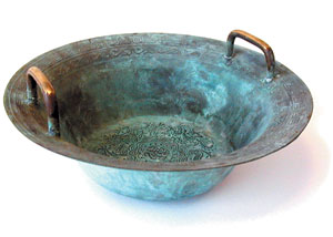


 Posted by Tami O'Connor
  by: Martin Sagendorf