How do I make the most out of my students’ time in school? I’m a substitute teacher!
On Friday afternoons, I am responsible for supervising a group of fifth grade students waiting for their buses to be called. We usually get about 25 minutes together, and I was often looking for ways to keep this period of time productive, fun and manageable. I am a lover of science, and I knew my students were too, so this seemed like the best direction to head in. But, I had a problem; as a substitute my days often involve moving from class to class with only a bag. This meant my science plans had to be small, flexible and accommodating for little set-up or clean-up time. So, after using a couple of Educational Innovations science products in my college class, I had a plan. On-the-go science with one Boi!nk.
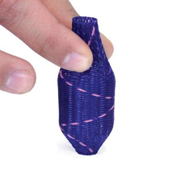
What is a Bo!nk?
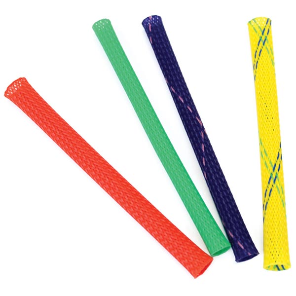
Bo!nks are plastic woven tubes about five inches long. When compressed on a surface, such as a desk or your hand, and then let go, the Bo!nk shoots through the air!
How did I use it?
I started off by displaying the Bo!nk to one of my students. I demonstrated how they could use it and encouraged them to experiment with it. Students who were usually consumed with conversation began to take notice. Slowly, one by one, my students were pulling up their chairs to figure out what this thing was. They each took a turn with it and experimented with the ways they could shoot it up in the air, who could make it go the farthest, what would happen if they compressed it this much or that much, and so on. Conversations began to arise with investigative thinking and I started to fill-in some of their questions. I was able to discuss the concept of potential elastic energy with my students and relate it to the Bo!nk they were all so fascinated with. Despite it being a short activity, it was incredibly rewarding to see my students engaging with introductory levels to NGSS standards such as 4-PS3-4 & 3-5-ETS1-3 action-reaction concepts and MS-PS3-5 presenting their own experimental evidence on why their methods of compression worked the best. It is exciting to know that if I bring this Bo!nk back to their classroom, they will have the prior knowledge of potential energy to discuss energy conversion, in this case to kinetic energy. And, they had fun! My students, who often sat in small, separated groups, antsy to leave school, had gathered with me due to their own interest. What may not be traditionally seen as a science lesson became a great groundwork to build on.
Opportunity
I keep this Bo!nk in the front pocket of my backpack and have a Reaction Rocket packed for our next mini-lesson. I appreciate how something so small can make such a difference, both engaging and providing hands-on activities for my learners. In 25 minutes, and with one plastic tube, my students began to build their knowledge in energy. My on-the-go science bag is ready for the next opportunity, no matter how short or small.


 Posted by Tami O'Connor

 Want to get your students revved up over the science of sound? This area of science has so much to explore, with more advances every day. Enjoy this collection of news related to recent discoveries about sound and waves.